Question1)
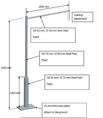
First figure shows the impression of one of many lifting arrangements produced and used at a steel fabrication workshop. It was manufactured to lift a maximum of 50 kg and due to a product line change, it needs to be modified to lift a maximum mass of 100 kg. Furthermore, the lifting mechanism at the loading point needs to be changed to a motor-driven winch which weighs 26kg. This motor driven win ch can accelerate a loads of 100 kg to 0.8 m/s2 in 1 second. Due to these changes, the factory manager needs to know whether the present lifting cranes can be modified as quickly as possible using only the left over pipes that had been purchased to manufacture thethe original lifting cranes. Your task is to provide the manager with a suitable proposal.
The required design constraints are as follows:
Function of the existing cranes:
A loading block is attached as shown to Pipe 3. The load will be raised from the floor level to a height of 1.5 metres. Do not consider the geometry of the load at this stage. Pipe 2 is not attached to the base plate and free to rotate inside Pipe 1. Do not consider the plate attachment to the floor, assume pipe 3 is welded to a perfectly rigid plate. Pipe 3 is rigidly connected to Pipe 2 by means of welding etc.
Available materials for modifications:
Materials: A few lengths of each of Pipe1, Pipe 2 and Pipe 3. (All pipes are steel with Ultimate Strength is 320 MPa, Yield Strength 280 MPa, Shear Strength 248 MPa, E= 200 GPa, Poisson’s ratio =0.3, Density 7880 kg/m3)
Design Criteria:
Part 1
1) Use only your knowledge of the fundamentals of stress analysis. (pre-requisite MEC2402 or equivalent)
2) Do not use any FEA softwarefor this task. Only hand calculations using fundamental formulas will be accepted. Use your fundamental knowledge in Stress Analysis. Strictly, do not use design formulas provided in design calculations, software orstandards. Use suitable assumptions where required.
3) You have to list all your assumptions and highlight them. You are free to make justifiable assumptions to resolve statically indeterminate situations or problems. You also need to write and identify the parameters used in your fundamental equations .
4) Provide suitably neat hand sketches where necessary and the final proposal must be sketched clearly. CAD packages can be used to present your design, but clearly define features with comments where appropriate. You are free to assume general engineering workshop processes are available for implementation of your modifications.
5) Calculate required lengths of materials and provide a cutting list.
Design Limitations:
The overall size of the crane must not be changed. The height and reach of the loading point is to remain the same. Original parts must remain and you are allowed additions such as corner plates, , bracing , re-enforcing etc. The maximum stress level of any component needs to be less than 75 MPa. If you can’t maintain the max. stress level under the specific level, you need to justify it Also you need to limit the vertical and horizontal displacement at the loading point less than 50 mm.
Part 2
Create a suitable model with beam elements and perform an FEA for:
1) Original crane arrangement
2) Modified crane arrangement (Part 1)
Your report should include:
• Hand calculations with sketches etc. for original crane – Part1
• Sketch of modified crane and hand calculations to show stress levels after modifications – Part 1
• Tabulate necessary/critical stress levels and location before and after modification (referring to your sketch) – Part1
• Explain FEA analysis following a standard FEA reporting format.
• Tabulate FEA results and compare FEA results with hand calculations
• Conclusions
Question 2
Second figure shows rough sketch of the selected representative critical part of a “Quick Coupler” (of an earth moving equipment) made with cast steel. You need to perform FEA analysis to estimate critical stress levels at given operational conditions. You can assume applied load as P = 3kN.
Your tasks: (Follow FEA reporting format where necessary)
1) Perform an FEA analysis for portion of the Quick Coupler with suitable constraints. (Hint: You can assume the sketch (b) represents the actual loaded component of the coupler. this critical part is taken from the circled area. You can consider the surfaces below the centre line (CL)s to be free and the top surface of the sketch to be rigidly connected to the larger body of the coupler)
2) Estimate the stress level at point A using your knowledge in “Stress Analysis”. Use only the given dimensions, and list clearly your assumptions and justify them.
3) Tabulate and compare FEA results with manually calculated values. Explain the differences in the answers you determined from FEA and manual estimates. Justify your comments.

(b)
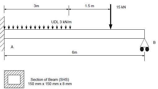
Question 3
Your task: (Follow FEA reporting format where necessary)
1) You need to sketch shear force and bending moment diagrams and estimate maximum bending and shear stresses acting on the beam using your knowledge in beam analysis. Please note that this beam problem is statically indeterminate. However, you can solve this problem using manual methods. Also write standard second order differential equation for elastic curve for the deflection of beam AB and deduce an equation for beam deflection. (Take E=200 GPa)
2) Perform a 2D FEA (Beam analysis) and compare FEA results and manually determined values for reactions at A and B and the deflection at mid-point of the beam. (Tabulate your results)
3) Compare your FEA results with manually calculated values.