A three generator power supply system is connected to a bus network operating at a common voltage of 220 kV. The network is shown in first Figure below.
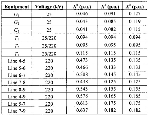
The neutral of each generator is grounded through ay'0.065 p.u. reactor. The generators are not loaded and are running at rated frequency and voltage. The system sequence impedance data on a common base of 220 kV and 100 MVA are given in Table Qla. A double line to ground fault occurs, between the phases detailed in Table second and ground, at the bus shown in first Figure, through a fault impedance ofy'0.085 p.u.. Assuming the prefault bus voltages as 1 p.u., calculate
a) The 9x9 admittance matrices for the zero, positive and negative sequence circuits;
b) Zkk for each of the zero, positive and negative sequence, where k is the number of the bus on which the fault occurs.
c) The fault current;
d) The current delivered during the fault by the generator detailed in second Table ;
e) The voltage at the bus detailed in second Table during the fault; and
f) The current in the line detailed in second Table during the fault.
Software that may be used is Matlab, Mathematica or Excel.
The format of file names submitted is to be as follows:
"StudentName StudentNumber.file extension'
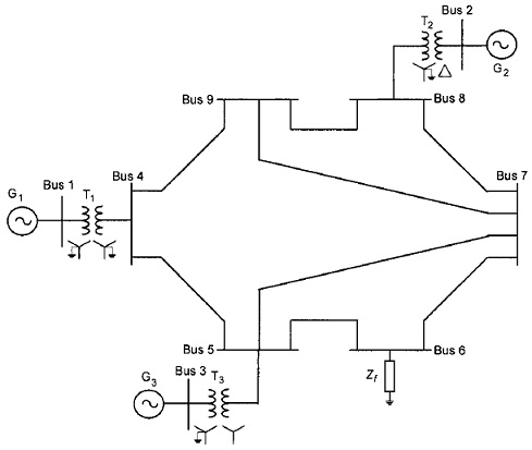
Table: Power system parameters
Table
Fault b) Generator c) Bus d) Inter bus
Name phases current voltage current
Bari a, b 2 1 5,6
Q2 A single phase transmission line consists of 5 conductors as shown Figure below.
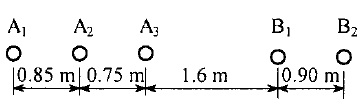
Conductors A1 to A3 are solid with a radius of 2.0 cm each and conductors B l and B2 are the return conductors, which are also solid, with a radius of 2.5 cm each.
A good approximation for the inductance of the circuit is given by
L=μ0/2π =ln GMD/GMRA +μ0/2π InGMD/GMRB.
The inductance so calculated is predicated on equal current distribution in the A conductors and in the B conductors. Starting with Equation
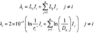
Calculate a more accurate value for the inductance that does not rely on this assumption and hence calculate the current distribution within each of the A and B conductors. State any assumptions made and the justification for the assumption.
The circuit is not transposed and the effects of earth may be neglected. The current may be assumed to be uniformly distributed throughout the conductor, i.e. skin and proximity effects may be neglected.