Question1)
Wave Retarders in Tandem
Write the Jones matrices for the following retarders:
(a) A π/2 wave retarder with the fast axis along the x direction.
(b) A π wave retarder with the fast axis at 45° to the x direction.
(c) A π/2 wave retarder with the fast axis along the y direction.
If these three retarders are placed in tandem, with (c) following (b) following (a), find the resulting rotation. What happens if the order of the three retarders is reversed?
Question2)
Maximum Extraordinary Effect
Determine the direction of propagation in quartz (ne = 1.553 and no = 1.544) at which the angle between the wave vector k and the Poynting vector S (which is also the direction of ray propagation) is maximum.
Question3)
Double Refraction
An unpolarized plane wave is incident from free space onto a quartz crystal (ne = 1.553 and no = 1.544) at an angle of incidence 30°. The optic axis lies in the plane of incidence and is perpendicular to the direction of the incident wave before it enters the crystal. Determine the directions of the wave vectors and the rays of the two refracted components.
Question4)
Transmission Through a LiNb0 3 Plate
Examine the transmission of an unpolarized He-Ne laser beam (λo= 633 nm) normally incident on a LiNb0 3 plate (ne = 2.29, no = 2.20) of thickness 1 cm, cut such that its optic axis makes an angle 45° with the normal to the plate.
a) Find out the lateral shift at the output of the plate and the retardation between the ordinary and extraordinary beams.
b) Sketch the beams
Question5)
Field Distribution
The transverse distribution um(y) of the electric-field complex amplitude of a TE mode in a slab waveguide is given by:
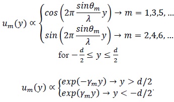
Derive an expression for the ratio of the proportionality constants. Plot the distribution of the m = 0 TE mode for a slab waveguide with parameters n1 = 1.48, n2 = 1.46, d = 0.5 μm, and λo == 0.85 μm, and determine its confinement factor (percentage of power in the slab).
Question6)
Coupling Coefficient between Two Slabs
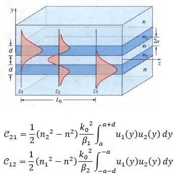
a) Find out the coupling coefficient between two identical slab waveguides of width d = 0.5 μm, spacing 2a = 1.0 μm, refractive indexes n1 = n2 = 1.48, in a medium of refractive index n = 1.46, at λo = 0.85 μm. Assume that both waveguides are operating in the m = 0 TE mode and use the results of Ques. 5 to determine the transverse distributions.
(b) Determine the length of the waveguides so that the device acts as a 3-dB coupler.
Question7)
Modal Dispersion in Step-Index Fibers
Find out the core radius of a multi-mode step index fiber with a numerical aperture NA = 0.1 if the number of modes M = 5000 when the wavelength is 870nm. If the core refractive index n1 = 1.445, the group index N1 = 1.456, and Δ is approximately independent of wavelength, determine the modal-dispersion response time σT for a 2-km-Iong fiber.
Question8)
Laser-Induced Breakdown Spectroscopy
Laser-induced breakdown spectroscopy (LIBS) is a type of spectroscopy that uses plasma generated by a laser pulse. A schematic of a LIBS system is shown in the figure below. The laser is focused on the sample and forms plasma, which atomizes and excites samples. LIBS has the capabilities of analyzing any material regardless of its composition (solid, liquid or gas). When a material breaks down and forms plasma of sufficient temperature, it emits light at characteristic frequencies (spectrum) that corresponds to the material. LIBS can (in principle) detect all elements, limited only by the power of the laser and the spectral sensitivity of the spectrometer & detector. The detection limit of the LIBS spectrometer is a function of a) the plasma temperature b) spectral pass band of the optical system, and c) the strength of the spectral emission being viewed.
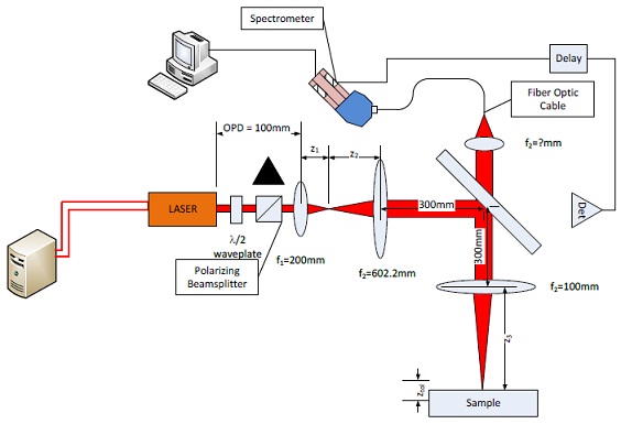
The LIBS system presented in Figure 1operates by focusing the laser onto a small part of the sample with sufficient power to ablate a very small amount of material.
Typically only a few nanograms of material ablated from the sample. This ablated material generates a plasma plume with temperatures in excess of 100,000 K. This plasma quickly cools to a temperature in the range of 5,000–20,000 K. At these temperatures the plasma plume is imaged. When the plasma is first formed it emits a continuum of light (i.e. white light) When the plasma cools and expands the spectral lines of the elements present in the plasma start to be observable. The delay between viewing the emission of continuum radiation and the spectral signature of the materials present is approximately 10μs from the laser pulse.
Design
Part 1 System Understanding
Referring to above Figure describe the purpose of the following subsystems, identifying each component in the path.
Transmission path:
Receiver Path:
Transmission Path
The laser source is a 1064nm Nd:YAG laser with a pulse width of 10ns. The average output power of the laser is 750W. The waist location is at the output window of the laser and has a diameter of 1mm. Assuming that it takes an intensity of 3.4 GW/cm2 to ablate the surface of the material of interest, what is the diameter of the beam on the sample? What F# is necessary to achieve this spot size? If the focal length of the lens is 100mm what is the Diameter of the lens (f3)? If the output of the laser has a diameter of 1mm and is a waist of the laser, determine the distances z1 and z2. Determine the distance z3. Calculate the radius of the beam assuming a Gaussian profile. Assuming it takes more than 75% of the peak intensity to form plasma, determine the tolerance on the sample location. (How accurate do you need to place the sample to get a signal?)
Receiver Path
One of the advantages of LIBS is that spectrometer which is used to analyze the plasma spectrum can be separated from the event by a distance with the use of a fiber optic cable. Assume for this design that the fiber optic cable is an 8/125 cable made of fused silica. For the purpose of this problem take the index of refraction of the core to be 1.46 and the cladding to be 1.42. What is the NA, the acceptance angle, θc, and ¯θc of the fiber? How many modes propagate down the fiber? Using this information, what is the focal length of the lens used to focus the light from the plasma into the fiber? At the other end of the fiber is a grating, lens, and linear CCD array. Sketch the configuration of this system used to collect the light diffracted by the diffraction grating onto the CCD Array. The grating has a Λ= 2000nm. What is the range of angles diffracted for a wavelength range from 400nm to 1000nm? Supposing that each pixel of the CCD array is 5 microns and that there are 4096 pixels in the linear array. What is the focal length of the lens? Find the wavelength resolution of the CCD Array?