Problem 1:
1. This first problem is similar to the first Smith chart example handed out in lecture but there is no perfect electric conductor in this homework problem. Use the Smith chart to solve the following problem where all regions have zero conductivity, the plane waves propagate in the ±z direction, they are polarized in the +x direction and the frequency of excitation is 12.3x10⁹ Hz. Give narration on non-Smith Chart paper and label copious numbers of points on your Smith Chart(s). Use more than one Smith Chart if your first one gets cluttered.
Relative permittivity values for regions "a", "b" and "c" are 3.7, 13.2 and 8.4, respectively. Relative permeability values for regions "a", "b" and "c" are 22.4, 48.5 and 35.8, respectively.
i) Draw the analogous DPTL model that represents this plane wave problem.
ii) Use a Matlab m-file to calculate intrinsic impedance, speed of light, wavelength and β for regions "a", "b" and "c". Include a copy of your m-file in your solution for this problem.
iii) Using a Smith Chart not a calculator, find SWR in regions "a" and "b".
iv) Using a Smith Chart not a calculator, find the complex reflection coefficients (magnitude and phase angle) at the "b/c" interface and at the "a/b" interface.
v) Give the locations of all Exmin and all Exmax that you find in region "b". If you find none of these mins or maxs then clearly state that fact.
vi) Give the locations of the Exmin and the Exmax that are closest to the "a/b" interface but are located in region "a". Note that you should find one of each.
Problem 2:
2. Consider the radome shown at our SharePoint site:
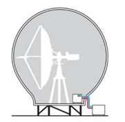
Using plane wave theory and a plastic that has relative permeability 1.0 and relative permittivity equal to two times the day of the month of your birthday (the 2 avoids making your radome out of air.) Specify your radome design by giving its wall thickness. Assume that the local building code states that the wall thickness for any such structure must be at least 1.75 cm. Justify your design with a narration and a Smith chart that is clearly labeled. Your narrationshould describe the labels you have added to your Smith chart. Assume that the operating frequency is 15.8x10⁹ Hz and that air permeates the region inside and outside of the radome but that the walls of the radome are solid plastic.
For the following three problems, please do your work without the Smith Chart but with vector phasors. When appropriate, convert final answers to explicit time dependence after completing your work in vector phasor format.